|
DESIGN TECHNOLOGY |
|
Besides myself, an electronic design engineer, two of our modelers are also talented electronic technicians. This gives PMD a BIG advantage over most all the other model building companies out there. When it comes to the wiring and animation part of the construction, you will definitely see the difference. With the full resources of CIRCUITRON at our disposal, virtually any kind of control and signaling systems can be implemented. If we don’t already stock the circuitry necessary, we can custom-build it. You will be amazed at the results! As you check with other model-building firms, you will quickly realize that most of them avoid electronics entirely (because they are not comfortable with it) or utilize very simple circuitry to implement only rudimentary control and signals. The level of detail provided by this approach is very limited, and this is one area where I am not afraid to get up and “toot our own horn”. You will find that a PMD constructed layout will have all color coded wiring, neatly bundled and ty-wrapped per electronic control industry standards. A complete wire run list and schematic diagrams of all custom electronics can be provided at completion.
|
|
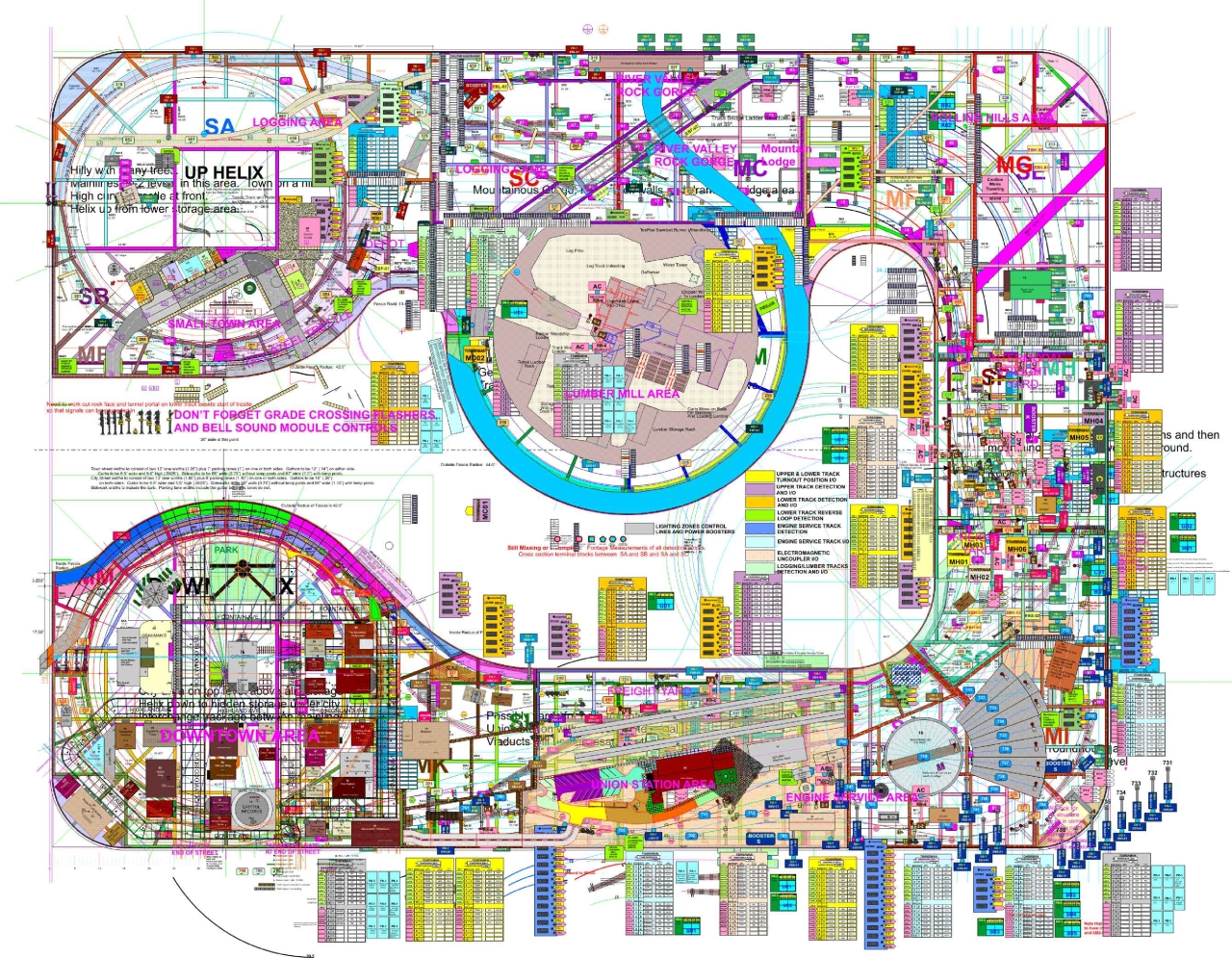
Now, if you have read our Sidebar disclaimer, we really DO use Computer Aided Design for virtually all our projects. The biggest advantage it provides is the ability to quickly make changes to a completed set of plans without having to re-draw everything. For that reason, I wouldn’t give it up for anything. We have seven computer systems in operation here at Circuitron / PMD. In our Engineering area, we have two custom built high speed, huge memory machines to run our CAD systems and graphics processing. Like all the computers here, these machines are networked for easy file transfer. Also in the Engineering area, we have a 42” wide format color plotter as well as two high resolution inkjet printers and a 1200 dpi color laser printer. The big plotter can create full size templates of our layout designs when needed and the inkjets and laser are capable of manufacturing custom signage and decals in black and white or color with extremely fine type in any of the thousands of fonts we have available. Although we use a couple of the model railroad design software packages extensively, we generally import the trackplans into CorelDraw and produce multi layered drawings with all structures, roads, and electronics shown on separate layers. Our most ambitious project drawing to date consists of over 190 layers of objects with over 55,000 text characters and 56,000 graphic objects. It is drawn full scale in Corel, that is, 230 inches by 330 inches. Here is what it looks like with all the layers turned on and shrunk to 3%.
|

|
SIDEBAR Please do not be misled by some of the wild claims you may read about Computer Aided Design (CAD) and Computer Aided Manufacturing (CAM). The operative word here is Aided. CAD is just a tool, in many ways not significantly different from the draftsman’s table, scales and drafting equipment. It is, without a doubt, more precise than the best draftsman out there. It is not necessarily as quick. And, no amount of precision will make up for sloppy technique or lack of insight. Designing model railroad layouts is as much art as it is technical skill, and the CAD system does little to improve the operator’s artistic or design ability . |
|
Circuitron has been a Corel supported reseller of their products since version 2 (1991). Most of our layout files are drawn in CorelDraw X3 (13) which is the version Steve is most comfortable working in. However, we have more recent versions up through 2019 installed as well. There are a few features in the newer versions that are helpful at times. A third computer system is used for billing, time tracking, estimating, etc., and we have two more computers dedicated to driving our Laser engraver/cutter and our 3 axis 48” x 96” CNC router. [Photo here] Finally, we maintain two legacy computers with the capability of loading old files and formats. We now have the ability to design and program a part on the computer when there is no commercial equivalent available and then use the CNC or laser equipment to machine it out of wood, plastic or plaster. Multiple identical pieces are easy to generate this way and perfectly sized custom retaining walls, columns, bridge abutments, etc. are a snap. The CNC router allows easy profiling of all curved plywood sub-roadbed pieces cut to a precision of 1/100 of an inch. The computers are networked for easy file transfer, printing and archive backup. |